

How To Repair Switch Screen
Introduction
Follow this guide to supplant a cleaved or faulty screen on the Nintendo Switch game console. This procedure replaces both the LCD panel and the digitizer every bit a whole unit of measurement. To supplant just the digitizer, follow this guide. To replace just the LCD console, follow this guide.
The Switch uses JIS screws, merely y'all tin use a Phillips screwdriver in a compression. Be very conscientious not to strip the screw. iFixit's Phillips bits are designed to be cross-compatible with JIS-style screws.
Note: When you remove the shield plate, you'll demand to supervene upon the thermal chemical compound between the plate and the heatsink. Since normal thermal paste isn't designed to bridge large gaps, the closest replacement is K5 Pro viscous thermal paste. Yous will, however, demand regular replacement thermal paste for the CPU.
You tin complete this repair without removing the heat sink and the game card reader, just it makes disconnecting and reconnecting the LCD panel ribbon cablevision much more difficult. Keep this in listen when you perform this repair.
Note: This guide, and the part nosotros sell, are compatible with the original Nintendo Switch model released in 2022, as well as the newer refreshed model released in 2022 (model numbers HAC-001 and HAC-001(-01), respectively).
-
-
Press and hold down the small circular button on the back of the Joy Con controller.
-
While y'all hold down the push, slide the controller upward.
-
-
-
Continue sliding the Joy Con up until it's completely removed from the console.
-
-
-
Use a Y00 screwdriver to remove the four six.3 mm-long screws securing the rear panel.
-
-
-
Apply a JIS 000 commuter or an official iFixit PH 000 driver to remove the following screws securing the rear panel:
-
Ane 2.5 mm-long screw on the top edge of the device
-
Two 2.5 mm-long screws on the bottom edge of the device
-
-
-
Use a JIS 000 screwdriver or an official iFixit PH 000 driver to remove the two 3.viii mm heart screws on the sides of the device (one on each side).
-
-
-
Use your finger to flip up the kickstand on the back of the device.
-
-
-
Use a JIS 000 screwdriver or an official iFixit PH 000 commuter to remove the 1.half dozen mm screw in the kickstand well.
-
Close the kickstand.
-
-
-
Open the game card cartridge flap.
-
Lift the rear panel up from the bottom of the device and remove it.
-
-
-
Utilize a JIS 000 screwdriver or an official iFixit PH 000 commuter to remove the 3.1 mm spiral securing the microSD card reader to the device.
-
-
-
Use your fingers or a pair of tweezers to lift the microSD card reader straight upward from the device to disconnect and remove information technology.
-
-
-
Use a JIS 000 screwdriver or an official iFixit PH 000 driver to remove the six iii mm screws securing the shield plate to the device.
-
-
-
Use your fingers or a pair of tweezers to skin dorsum the piece of cream on the top edge of the device nigh the fan frazzle port.
-
-
-
Insert a spudger underneath the shield plate along the edge of the device.
-
Pry upwardly to lift the shield plate and remove it from the device.
-
-
-
Use the point of a spudger to pry the battery connector directly up and out of its socket on the motherboard.
-
-
-
Use a JIS 000 screwdriver or an official iFixit PH 000 driver to remove the three 3 mm screws securing the oestrus sink to the motherboard.
-
-
-
Carefully peel the two foam pieces stuck over both the heatsink and the fan away from the fan.
-
Insert the point of a spudger underneath the part of the foam that isn't stuck against anything,
-
Press the pinnacle of the foam with your finger to hold information technology in place.
-
Coil the spudger tip underneath the cream all the way to the other terminate of the foam to release information technology.
-
-
-
Use a spudger or your fingers to elevator the heatsink up and off the motherboard to remove it.
-
-
-
Use an opening tool or your fingernail to flip upward the small-scale, hinged locking flap on the digitizer cable's ZIF connector.
-
-
-
Use a pair of tweezers to slide the digitizer cable horizontally out of its connector on the game carte reader board.
-
-
-
Use the signal of a spudger to pry the headphone jack and game card reader connector straight upward to disconnect it from the motherboard.
-
-
-
Use a JIS 000 screwdriver or an official iFixit PH 000 driver to remove the three 3.i mm screws securing the headphone jack and game card reader board to the device.
-
-
-
Use a pair of tweezers or your fingers to remove the headphone jack bracket.
-
-
-
Apply a pair of tweezers or your fingers to remove the headphone jack and game card reader board.
-
-
-
Use an opening tool, spudger, or your fingernail to flip up the pocket-sized, hinged locking flap on the LCD ribbon cablevision ZIF connector.
-
-
-
Use a pair of tweezers to pull the ribbon cable directly out of its connector on the motherboard.
-
-
-
Employ an opening tool, spudger, or your fingernail to flip upward the small, hinged locking flap on the smaller LCD ribbon cablevision ZIF connector.
-
-
-
Use a pair of tweezers to pull the ribbon cablevision straight out of its connector on the motherboard.
-
-
-
Heat an iOpener and apply information technology to the bottom edge of the screen for around two minutes to to help soften the adhesive.
-
-
-
Apply a suction cup to the bottom-left corner of the screen.
-
Pull upwardly on the suction upward with strong, steady forcefulness to create a gap.
-
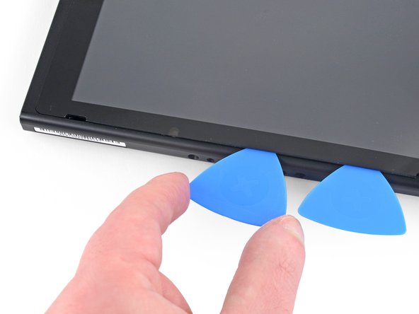
Insert the indicate of an opening pick into the gap, making sure to only insert the pick about 5 mm.
-
-
-
Slide the opening pick along the lesser edge of the screen to slice the agglutinative.
-
Get out the selection inserted to prevent the adhesive from re-adhering to the frame.
-
-
-
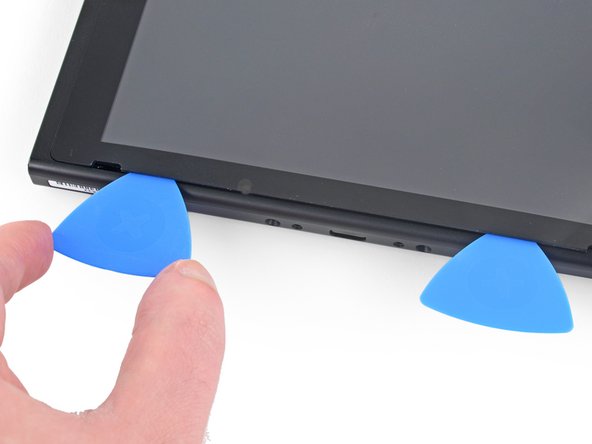
Insert a 2d opening pick into the gap to the left of the start pick.
-
Slide the opening pick back towards the left side of the device.
-
Leave the opening option inserted.
-
-
-
Heat the left border of the screen for around two minutes to help soften the adhesive.
-
-
-
Continue sliding the opening option around the bottom-left corner to slice the adhesive.
-
-
-
Go along sliding the opening pick along the left edge of the screen to slice to agglutinative.
-
-
-
Rut the pinnacle edge of the screen for effectually two minutes to help soften the adhesive.
-
-
-
Go along sliding the opening pick around the top-left corner of the screen to slice the agglutinative.
-
-
-
Go along sliding the opening pick forth the superlative edge of the screen to piece the adhesive.
-
-
-
Heat the right edge of the screen for around ii minutes to assistance soften the adhesive.
-
Place the flat end of a spudger into the gap along the left edge of the screen.
-
Carefully and slowly lift the left edge of the screen, opening it like a volume.
-
-
-
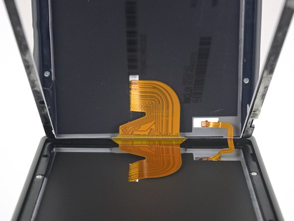
Lift the right edge of the screen straight off the device, threading the ribbon cables through the frame equally you practise so.
-


Conclusion
Compare your new replacement role to the original role. Y'all may need to transfer remaining components or remove agglutinative backings from the new function before installing.
To reassemble your device, follow these instructions in contrary order.
If your new screen doesn't work properly after y'all boot upwards the device, plow it back off and disconnect and reconnect the battery connector.
Take your e-waste product to an R2 or eastward-Stewards certified recycler.
Repair didn't go as planned? Try some basic troubleshooting, or enquire our Nintendo Switch Answers community for help.
Embed this guide
Choose a size and re-create the lawmaking below to embed this guide as a small widget on your site / forum.
Preview

How To Repair Switch Screen,
Source: https://www.ifixit.com/Guide/Nintendo+Switch+Screen+Replacement/140021
Posted by: cousarhiserfuld1987.blogspot.com
0 Response to "How To Repair Switch Screen"
Post a Comment